WAVESHAPE
Waveshape distortion synthesis.
in RTcmix/insts/std
quick syntax:
WAVESHAPE(outsk, dur, PITCH, INDEXMIN, INDEXMAX, AMP, PAN, WAVETABLE, TRANSFERFUNCTION, INDEXENV[, ampnormalize])
CAPITALIZED parameters are pfield-enabled for table or dynamic control (see the maketable or makeconnection scorefile commands). Parameters after the [bracket] are optional and default to 0 unless otherwise noted.
| Param Field | Parameter | Units | Dynamic | Optional | Notes |
|---|---|---|---|---|---|
| p0 | start time | seconds | no | no | |
| p1 | duration | seconds | no | no | |
| p2 | pitch | Hz or oct.pc * | yes | no | see note below |
| p3 | minimum distortion index | 0.0-1.0 | yes | no | |
| p4 | maximum distortion index | 0.0-1.0 | yes | no | |
| p5 | amp | absolute, for 16-bit soundfiles: 0-32768 | yes | no | |
| p6 | pan | 0-1 stereo; 0.5 is middle | yes | no | |
| p7 | reference to oscillator waveform table | reference to pfield table-handle | yes | no | |
| p8 | reference to waveshaping transfer function table | reference to pfield table-handle | yes | no | |
| p9 | index control envelope | - | yes | no | |
| p10 | amp normalization | - | no | yes | default: on (1) |
Parameters labled as Dynamic can receive dynamic updates from a table or real-time control source.
Author: Brad Garton; rev for v4, JGG, 7/22/04
WAVESHAPE produces sound using waveshaping, a type of distortion synthesis where an input waveform is modified by a transfer function to produce an output signal.
Usage Notes
The technical description of waveshaping is that an input signal, x,
puts out an output signal, y, by passing through a function defined as
y = f(x). So, for example, f(x) = x2 will exponentially expand the
amplitude of the incoming waveform (Dodge and Jerse, 1985).
What does this mean? Imagine a transfer function as a line drawn on a cartesian coordinate system:
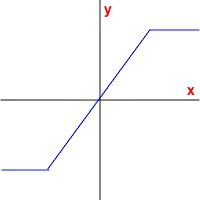
The x-axis is where the input values from the signal are located. These are then mapped onto te y-axis – the output values – by mapping from the x-axis to the transfer function curve and then over to the y-axis:
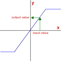
Note that if the input value goes above or below a certain point on the above graph, the output value will remain constant even if the input value increases beyond that point (positive or negative). This simple waveshaping distortion will result in “clipping” the input signal:
The “INDEXMIN” (p3) and “INDEXMAX” (p4) set the parameters for how the lookup/transfer function works. In the above example, the “INDEXMIN” was assumed to be 0.0 and the “INDEXMAX” was 1.0. This will use the full range of the x-axis input values, i.e. the whole transfer function. You may choose to use just a small portion of the transfer function for doing the x-axis -> y-axis mapping by setting these two values between 0.0 and 1.0.
The particular range of lookup values will also be determined by the “INDEXENV” pfield control envelope (p9). It determines how much of the range between p3 and p4 is used. Changing this dynamically can alter the spectrum of the note through time. For example, a control envelope that traveled from 0.0 to 1.0 back to 0.0 for the duration of a note with a transfer function like the one pictured above will gradually introduce distortion into the output wave and then gradually reduce it. All timbres produced by WAVESHAPE are harmonic spectra, however. No non-harmonic partials can be generated by waveshaping.
p8 (the “TRANSFERFUNCTION”) is a pfield reference to a table containing the transfer function to be used. These are generally constructed using the maketable scorefile command. Of special interest is the maketable(“cheby”, …) option. Chebyshev polynomials can help design transfer functions with particular harmonic characteristics.
The transfer-function process (called a “table lookup” by the way) also imparts an amplitude to the signal as the “INDEXENV” travels between 0.0 and 1.0. Because this is primarily used for determining the spectral character of the note, you may wish to use an independent amplitude envelope (done using the pfield-control capabilities of the “AMP” parameter, p5). To guarantee that a full output results from the waveshaping, the optional “ampnormalize” parameter (p10) can be set to 1 (this is the default, by the way). To turn off this normalization, set it to 0. Why would you want to turn this off? The amp normalization in this instrument can cause clicks at the beginning and ending of notes if you don’t set your amplitude envelope.
Any waveform may be used as an input function. The waveform table is specified in p7 (“WAVETABLE”).
Be aware that oct.pc format generally will not work as you expect for p3 (pitch) if the pfield changes dynamically because of the ‘mod 12’ aspect of the pitch-class (.pc) specification. Use direct frequency (hz) or linear octaves instead.
WAVESHAPE can produce mono or stereo output.
Sample Scores
very basic:
   rtsetparams(44100, 2)
   load("WAVESHAPE")

   ampenv = maketable("line", 1000, 0,0, 3.5,1, 7,0)
   waveform = maketable("wave", 1000, "sine")
   transferfunc = maketable("linebrk", 1000, -0.5, 300, -0.5, 200, 0, 200, 0.5, 300, 0.5)
   indexfunc = maketable("line", 1000, 0,0, 3.5,1, 7,0)

   WAVESHAPE(0, 7, 7.02, 0, 1, 20000*ampenv, 0.3, waveform, transferfunc, indexfunc)
   WAVESHAPE(0, 7, 7.021, 0, 1, 20000*ampenv, 0.7, waveform, transferfunc, indexfunc)
slightly more advanced:
   rtsetparams(44100, 2)
   load("WAVESHAPE")

   ampenv = maketable("line", 1000, 0,0, 3.5,1, 7,0)
   waveform = maketable("wave", 1000, "sine")
   transferfunc = maketable("cheby", 1000, 0.9, 0.3, -0.2, 0.6, -0.7)
   indexfunc = maketable("line", 1000, 0,0, 3.5,1, 7,0)

   WAVESHAPE(0, 7, 7.02, 0, 1, 20000*ampenv, 0.99, waveform, transferfunc, indexfunc)

   ampenv = maketable("line", 1000, 0,0, 1.5,1, 7,0)
   indexfunc = maketable("line", 1000, 0,1, 7,0)

   WAVESHAPE(4, 7, 6.091, 0, 1, 20000*ampenv, 0.01, waveform, transferfunc, indexfunc)
See Also
maketable, pchcps, MULTIWAVE, VWAVE, HALFWAVE, SYNC, WAVETABLE, FMINST, AMINST, WAVY, WIGGLE